Belkin F5D4076 Test Results
The Test Results from a Notified Body: Belkin F5D4076
Official The first PLT to pollute past 300MHz!
Here are the test results for the Belkin F5D4076, as determined by a highly respected laboratory which is also a UKAS Accredited Notified Body. A Notified Body is a lab with accreditation which allows it to state whether a Device Under Test passes or fails the strict levels agreed internationally which determine if goods can be sold in Europe.
Fortunately in this case, Belkin helpfully cite EN 55022 in F5D4076's Declaration of Conformity (DoC), so now we can check the claim against real test results and see if indeed the Belkin complies.
The details of the F5D4076's DoC document are of particular interest since Belkin have chosen to cite EN 61000 which is a generic standard for equipment which does not fall into any particular category or new equipment to market. However, Belkin have also cited EN 55022 which is a "Typed Standard" and supersedes a generic standard, rendering questionable why cite 61000 at all since they both reference CISPR22 levels?
First, a taste of some radiated emissions. A point worth noting is that these measurements mirror another set of measurements recently submitted by German broadcasters NDR and ZDF to the ITU Study Group WP6a. It is also worth noting that the document in question looks closely at the levels of PLT interference and is not at all favourable.
Whilst on the subject of noteworthy points, these results were obtained with the Belkins operating at 100Mbps; however it is known that the level of emissions rise with increasing data rates. More results will be published when available!
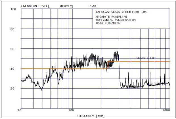
This first example is for the Belkin with an antenna set horizontally. The reason for this is that for any given "system" there will be a combination of electromagnetic radiation which can be very specific to the orientation of the receiving equipment's antenna. You will have noticed for example that the majority of TV antennas have the elements orientated in line with the horizon. If one were to rotate these through 90 degrees, the picture would likely fade to almost nothing, depending upon how strong the signal was. This principal is equally applicable to interference.
Given that the Belkin's DoC declares compliance with EN 55022, we have conveniently highlighted the limit lines for this Standard on the diagram. It should be noted that the span appearing above the word "Frequency" represents the part of the spectrum allocated to VHF FM Broadcasting, the Civil Air Band and DAB Radio Broadcasting. Oh dear...
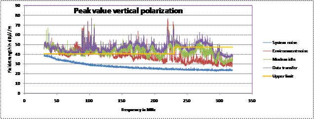
So let us take a look at the vertical component.
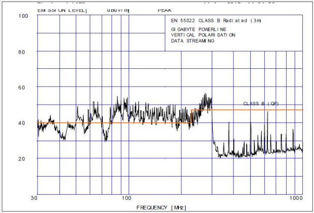
As is clearly visible in the diagram above, even more of the spectrum is polluted, however the same region mentioned previously has not escaped; this now shows that the orientation of the antenna is only having a more pronounced effect at lower frequencies. Just visible at the left hand side, the line breaches the limit just on the cordless telephone frequency too.
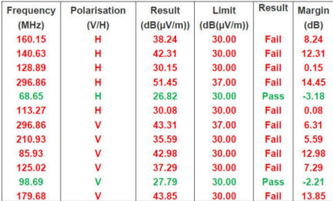
For those interested in the figures, a small table is presented for completeness:
The data above represents Radiated Emissions. This means radio-waves travelling though the air but this is only one half of the story (actually not even that!).
The other emission of consequence is Conducted. Some conducted emissions are wanted - like the signal coming down the coax cable from your TV antenna or satellite dish to your receiver; these are helpful, wanted. There is another kind though, and it is not at all welcome. A UKQRM member comments: "As an electrical engineer I quite often came across instances a few years ago where mains alarm clocks would suddenly and inexplicably start gaining or loosing time - hours per day in some instances. In the end it was determined that photoelectric sensors in the street lights were sending pulses back down the mains cables feeding the lights and the adjacent property and were 'messing-up' the alarm clocks time keeping circuit." This is just one example of an unwanted conducted emission - and its consequence. In a more contemporary setting, we are now seeing the conducted emissions from PLT and cheap consumer electronics slowing down broadband by increasing the error rate on the data.
In today's digital age when almost everything has complex circuits governing its operation it is more important than ever that these unwanted consequences are prevented and this is just what EMC is all about. To this end, it is not only the radiated signals which need to be monitored but the conducted ones too; indeed to some extent one does not exist without the other - radiated and conducted. In the interests of making sure that everything can work the way it is intended, these unwanted side effects need to be kept to a minimum so taking measurements of conducted emissions are equally important since this allows the manufacturers to cure the problems before they even happen!
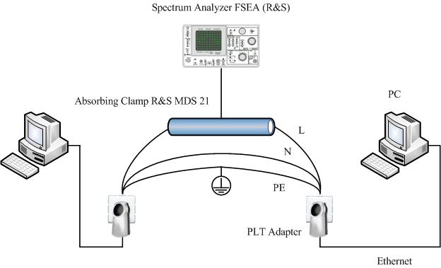
Here is an example of how Conducted Emissions are measured.
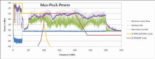
Here is a conducted example for the Belkin F5D4076. Do not confuse the red and yellow lines with the limit lines from the previous radiated example, these here have a different meaning outside the scope of this article. However it is possible to observe the correlation with the radiated example above; the deep null at roughly 30-40 MHz and the sharp drop at 300 MHz line corresponds closely to the radiated example.
Until now, common standards have only required the upper limits of conducted emissions to be set at 30 MHz; however in light of more recent developments in measurement technology, understanding of the complex interactions which can occur in EMC and concern for mutual operability, these limits have been extended much, much higher. Like all Standards based limits it comes with a transitional period but good engineering practice is to always meet the limits long before they become mandatory.
In this regard it seems that Belkin have shot themselves in the foot since their DoC is based on non-mandatory levels which it has failed to meet; thus the DoC as it stands is allegedly worthless.
Here are some further radiated emissions tests, which show the levels. These results were obtained in a location with a fair amount of local interference, not generated by the Belkins, however the results still speak volumes.
Until now, members of UKQRM have primarily focused on Conducted Emissions since these have been the weapon of choice for the EMC Engineer; and have been directly relevant to PLT since PLT was only creating electromagnetic disturbance below 30 MHz. However with the introduction of g.9960 and the Gigle chipset a whole new area of PLT interference needs to be scrutinised. How relevant Conducted Emissions above 30 MHz will prove to be to the PLT EMC argument is not clear; the prime reason Conducted Emissions have not previously extended above 30 MHz is that except for a complex area called surface wave technology, Conducted Emissions attenuate fairly rapidly above this frequency - the main reason being the energy radiates, plus due to higher losses in the non-conducting materials comprising insulated cables.
This has changed forever with the Gigle chipset and the Belkin adapters and you can be sure that much more material will accumulate on this site as the data becomes available.
![]() Back
Back
Page updated: 8th December 2020
Home
|
News
|
What is PLT?
|
Why the fuss?
|
What can I do?
|
Shame on you!
|
Videos
|
EMC Tests
|
EMCIA
EN55022
|
prEN50561-1:2012
|
Legislation
|
Truth & Lies
|
Adjournment Debate
Guest author DJ5IL: The Trojan Horse of the PLC-Lobby: FprEN50561-1
|
Doomed to Fail: FprEN50561-1